


Description
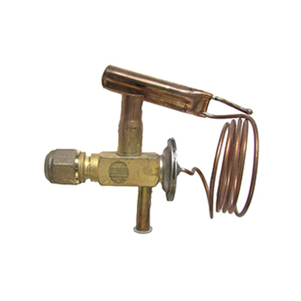
Rheem 180079 TX Valve
TX Valve Replacement

- Isolate power to the water heater.
- Remove the Storage Tank upper electrical access cover and confirm with a multi-meter across thermostat terminals 1 and 3 that voltage is not present.
- Integrated Models:
Remove the Heat Pump Module.Split Models:Remove the Heat Pump Module.Remove the screw retaining the flexible hose clamping bracket at the rear of the Heat Pump Module and remove the clamping bracket.Slide the flexible hoses out of the support bracket.Slide the entire Heat Pump Module to the right to disengage the feet from the retaining bolts.Pivot the Heat Pump Module away from the wall. Note: Take care not to kink the flexible hoses.Remove the 6 screws retaining the upper rear panel, release the saddles on the cable set and remove the upper rear panel. - All service calls to heat pump modules must include a check to ensure the Suction Line Brace is installed. If the Suction Line Brace is not installed, the Heat Pump Rework Kit must be installed as part of the service call. If a Heat Pump Rework Kit has previously been installed and only the Suction Line brace is missing, a Suction Line Brace must be fitted as part of this procedure.
- Where the suction line brace is fitted at the very top of the evaporator coil without screws, remove the brace. Using a pair of pliers, begin by straightening the bends in the corners of the evaporator coil end plates that stop the brace from moving upwards. Slide the brace up off the evaporator coil end plates, while gently tapping it at the bottom with a small hammer. Be careful not to damage the evaporator coil fins.
- Remove the insulation to expose the TX valve bulb and remove the bulb from the suction line.
- Recover the refrigerant from the sealed refrigeration system.
- DisconnectpipeworkandremovetheTXvalve.
- Braze the replacement TX valve into place, being sure to nitrogen purge. NOTE: The TX valve must be cooled whilst brazing pipework to prevent internal damage.
10.Attach the TX valve bulb firmly to the suction line at the 1 o‟clock position and refit insulation.
11.Replace the receiver / filter drier.
12.Pressurise the refrigeration system with nitrogen to 3000kPa and conduct a leak test.
13.Evacuate system to 500 microns of mercury (65Pa absolute) for at least 30 minutes.
14.Recharge the system with the correct refrigerant.
15.Reassemble in reverse order of above, ensuring to re-make the small bends in the corners of the evaporator coil end plates that stop the suction line brace from moving upwards.
WARNING: The suction line brace MUST be fitted whenever the heat pump is in operation.
16.Restore power and allow the heat pump to run for 10 minutes.
17.Check the TX valve superheat setting and adjust if necessary
18.Isolate power; remove gauges and refit/re-install the Heat Pump Module.
19.Check the flexible hose connections for water leaks.
20.Refit the Heat Pump Module access cover and restore power supply to the water heater.


